
Realize Medical

Support

Tutorials & how-to guides.

Step-by-step guidance for working in Elucis — from importing DICOM data to segmentation, rendering, and capture. Have a question we haven't covered? Email support@realizemed.com.

Realize Medical · 2019-05-28

Importing DICOM Images from your PC

Follow these steps to import DICOM images into your project.

1. Create a New Project

  • Click New Project.
  • Name your project.

2. Select Image Location

  • Press Select Path.
  • Navigate through your PC to the folder where your DICOM images are stored.

3. Review Your Images

  • Once the images have uploaded, use the scroll bar on the right to cycle through them.
  • Confirm that the image set is correct.

4. Finalize Import

  • Press Create to complete the import.

Managing Multiple DICOM Image Sets

  • Set a Primary Image — double-click on an image thumbnail to make it your primary image. A green box will appear around the thumbnail.
  • Set Secondary Images — check the box in the upper-right corner of a thumbnail to mark it as secondary. A blue box will appear around the thumbnail.
  • You can add as many secondary image sets as you need.
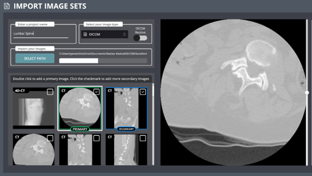
Elucis Import Image Sets dialog showing DICOM project setup with primary and secondary image thumbnails.

Realize Medical · 2019-05-28

Aligning Multiple Image Sets

When multiple image sets are imported, Elucis will automatically align them using their DICOM information. If they don't align automatically, follow the steps below to manually align them.

1. Automatically Align Image Sets

  • Open the Images tab.
  • Select Image Registration.
  • On the surface plane, locate Registration Type and select Automatic.
  • Press the Auto Register button. This will automatically align the secondary image to the primary image.

2. Copy Alignment to Additional Image Sets

  • Open the Images tab.
  • From the Secondary Image Set dropdown, select the series you want to align.
  • On the surface plane, locate Copy Registration From, followed by the name of the previously aligned secondary image set.
  • Press Copy to align the image to the same position as the previous set.
  • Repeat this process for all remaining secondary image sets.

Realize Medical · 2019-05-28

Manual Image Co-Registration

When primary and secondary image sets are imported, Elucis automatically detects shared DICOM properties and aligns the images. When manual adjustment is desired, use the Image Registration tools.

1. Access the Image Registration Tools

  • Open the Controller Menu on your non-dominant hand.
  • Select the Images tab.
  • You'll see both your Primary and Secondary image sets, along with Fusion Settings at the bottom of the menu.
  • Fusion Settings let you display the Primary, Secondary, or a blend of both image sets, and use different blending modes to enhance anatomical visibility.

2. Open the Image Registration Panel

  • In the Images tab, select Image Registration.
  • On the surface plane, you'll find two registration options for aligning the images.
  • Adjustments only affect the secondary image set. The primary image remains fixed.

3. Use the Movement Gizmo

  • Translation Tool: move the secondary image along the X, Y, and Z axes.
  • Rotation Tool: rotate the image around the same axes.
  • Spin Tool: fine-tune the image orientation.

4. Fine-Tune Image Positioning

  • Extra Precise Mode: requires larger stylus movements for small positional changes.
  • 1 mm / 1° Mode: enables movement in exact 1-millimeter or 1-degree increments.

5. Align Image Sets in 3D

  • In the Images tab, enable Ghost View for both the Primary and Secondary image sets.
  • Use the Movement Gizmo to line up visible anatomical borders on the ghosted views.
  • Once alignment looks correct, press Save State on the surface plane. This locks both image sets into position.

Realize Medical · 2019-05-28

Thresholding Tutorial

Setting a proper threshold is one of the most important steps when segmenting a model that accurately reflects the anatomy of interest. The Threshold Scroll Bar in Elucis defines values that correspond to the tissue densities you wish to include.

1. Preparing to Set a Threshold

  • Open the Controller Menu.
  • Click Models, then create a New Structure.
  • On the Stylus Menu, select the Add button.
  • At the bottom left of the Surface Plane, select Display Threshold. Pink regions represent your current threshold range.

2. Understanding the Threshold Scroll Bar

  • Two slider buttons define the minimum and maximum range of your threshold.
  • Closer together → narrow range; further apart → wider range.

3. General Threshold Ranges (CT Data)

  • Left side → radiolucent structures (air, fat, low density).
  • Middle → soft tissue (muscle, organs).
  • Right side → radiodense tissue (bone, contrast media, metal).
  • Example — segmenting myocardium while excluding chamber contrast: move the left slider until the myocardium is highlighted, then move the right slider until contrast regions are no longer highlighted.

4. Thresholding in MR and Echo Data

  • Use the left slider to broadly capture the tissue of interest.
  • Adjust the right slider to refine and isolate the desired region.

5. Fine-Tuning Threshold Values

  • Gently drag the slider buttons for small adjustments, or
  • Use the Minimum and Maximum toggles on the right-hand side of the surface plane.

6. Reducing Noise

  • Check the Reduce Noise box for cleaner, more defined borders.
  • Noise reduction applies only to the threshold visualization, not the image data itself.

Realize Medical · 2026-03-16

Rendering and Positioning an Echo Image Set

Follow these steps to volume render an echo image set and accurately position it within a segmented heart model.

1. Open the Echo Image Set

  • Open the Controller Menu.
  • Select the Images tab.
  • Locate the image tab containing the Echo image set and press Volume Rendering.
  • Open the drop-down menu and select the Echo preset.

2. Adjust the Rendered Model

  • Crop sliders: adjust the visible portion of the volume.
  • Offset sliders: modify the depth and position of the rendering.

3. Apply a Mask to Shape the Cardiac Valve

  • Open the Stylus Menu.
  • At the bottom, find the Mask tool section.
  • Press Add Mask to begin shaping the rendered model.
  • Use the middle finger trigger on your non-dominant hand to toggle between Add Mask and Remove Mask modes.

4. Reposition the Valve Within the Segmented Model

  • Open the Controller Menu again.
  • Go to the Images tab and select Image Registration.
  • Enable the Use Free Hand toggle to freely position the rendered valve within the segmented heart model.

5. Final Positioning and Alignment

  • Open the Images tab and disable the Clippable toggle.
  • Create a new clip plane that intersects the segmented heart model.
  • Use this plane to position the valve precisely.
  • Align the model in relation to the CT scan using the planar surface as a reference.

Realize Medical · 2026-03-16

Screen Capture and Recording

Document and export specific model views for use in presentations, educational materials, or quick visual references — including video, snapshots, and rotational image series from desktop and VR.

1. Navigate and Prepare Your Model

  • Rotate the model using the right mouse button.
  • Zoom in/out using the scroll wheel.
  • Center the model by pressing both the scroll wheel and right mouse button simultaneously.

2. Adjust Screen Visualization

  • Open the Screen Visualization Options tab on the right-hand side.
  • Show or hide the surface plane and image volume box.
  • Adjust and orient the light source.

3. Access the Content Recording Tools

  • Open the Content Recording tab to view the three capture modes: Start Video Recording, Screen Snapshot, and Rotational Series.

4. Record a Video

  • Press Start Video Recording. A flashing 'Recording' signal appears at the top of the screen.
  • Rotate and manipulate the model as needed.
  • Open the Content Recording tab and press Stop Video Recording. A small zoom visualization confirms the video has been saved.

5. Capture a Still Image

  • Open the Content Recording tab.
  • Press Screen Snapshot. The zoom visualization confirms the capture has been saved.

6. Review and Export Captures

  • Open the Snapshots and Recordings button on the left-hand side.
  • Click any thumbnail to open a review window where you can inspect and add annotations.
  • Click the top-left circle on each thumbnail to export, or press Select All, then Export Selected.

7. Capture a Snapshot in VR

  • Open the Stylus Menu and press the Camera button.
  • Position the shutter screen as desired.
  • Adjust field of view, surface plane visibility, and background color.
  • Squeeze the index finger trigger on your dominant hand to capture.

8. Capture a Rotational Series

  • Open the Content Recording tab and select Rotational Series.
  • Choose the export format — PC image or DICOM files (DICOM can be exported directly to an integrated PACS system).
  • Configure field of view, centering, file format, image resolution, number of rotational steps, and series name.
  • Preview using the Preview button, then press Export to save to your PC or PACS system.

Realize Medical · 2026-03-16

Segmenting a 4D Heart Model

Create and segment a 4D heart model from your image series.

1. Create a New Structure

  • Open the Models tab in the Controller Menu.
  • Create a new structure.

2. Access the Image Series

  • Open the Images tab.
  • Scroll to the bottom to locate Time Series Settings.
  • Set the image series to Static (manually cycle phases) or Dynamic (auto cycle).
  • For efficiency, set the series speed to its maximum before beginning.

3. Begin Segmenting

  • Open the Stylus Menu and select the Add Tool.
  • On the surface plane, ensure Use Threshold and Display Threshold are both enabled.
  • Adjust the threshold to match the contrast-filled heart chambers.
  • Begin segmenting — the segmentation applies across all image phases.
  • Tip: segmentation can also be performed in 3D, though this can be computationally demanding.

4. Clean Up the Segmentation

  • Open the Images tab and set Time Series Settings to Static.
  • Open the Stylus Menu and select the Select-Connected Tool.
  • Squeeze the index finger trigger on your dominant hand and tap the blood volume to select.
  • Tap Delete Unselected on the surface plane to remove floating anatomy.
  • Repeat for each phase.

5. Build a Shell Around the Blood Volume

  • Open the Operations tab in the Controller Menu.
  • Under Single Structure Operations, select the blood volume, change the operation to Shell, and set your shell thickness.
  • Ensure Apply to All Phases is enabled.
  • Press Execute. A new structure appears in the Models tab.

Realize Medical · 2026-03-16

Separating Models into Individual Structures and Colours

The Select/Split function in Elucis is a powerful and efficient method for separating complex models into individual anatomical structures.

1. Prepare the Model

  • Open the Controller Menu.
  • Ensure the model you intend to split is the active structure.
  • Open the Stylus Menu and press the Select button.

2. Understand the Preview and Selection Toggles

  • Show Selection — displays both the full model and your selection.
  • Preview Inside — shows only your selection, hiding the rest of the model.
  • Preview Outside — shows the model minus your selection.

3. Refine the Selection

  • Preview Inside: Grow Selection adds anatomy; Shrink Selection removes anatomy.
  • Preview Outside: Grow Selection removes anatomy from the model; Shrink Selection adds it back.
  • These complementary tools enable accurate boundary definition between adjacent structures.

4. Split the Model

  • Turn to the Work Surface.
  • Locate the Destination toggle next to the Split button and ensure it reads New Structure.
  • Press Split. Your selection changes color, indicating it has been separated.
  • In the Models Menu you'll see a new structure labeled 'Intersection.' Rename as desired.

5. Transfer a Selection Between Structures

  • Ensure the source structure is active.
  • Use the Select Tool to highlight the portion you wish to transfer.
  • On the Work Surface, cycle the Destination toggle to the target structure.
  • Press Split. The selected anatomy transfers to the chosen destination.

Realize Medical · 2026-03-16

Synchronizing Image Sets Before Segmentation

Important: image syncing must be completed before performing segmentation.

1. Open the Image Tabs

  • Open the Controller Menu.
  • Select the Images tab.
  • Under both the Primary and Secondary image tabs, click the clock icon to open Phase Timing Settings.

2. Set the Cardiac Cycle Start Point (Primary Image)

  • In Phase Timing Settings, the green arrow above the phase box marks the reference point for the start of the cardiac cycle.
  • Use the left and right toggles next to Cycle Start Index to adjust the start of the cardiac phase.
  • For this example, set the beginning of the cardiac cycle to atrial systole.

3. Adjust the Secondary Image Timing

  • Open the Phase Time Settings for the Secondary Image.
  • In an echocardiography series, display one full cardiac cycle.
  • Cycle through the image phases to identify the start and end of one cardiac cycle.
  • Use Trim from Start or Trim from End to remove extra phases outside of the single cycle.

4. Synchronize with the CT Scan

  • Compare the cardiac phase of the CT scan with that of the echo.
  • Open the Phase Timing Settings for the Secondary Image.
  • Using Cycle Start Index, locate the image phase showing the open mitral valve. The green arrow indicates synchronization with the CT scan.

5. Verify Synchronization

  • Visually inspect both image sets to confirm the phases align.
  • Adjust the Cycle Start Index for the secondary image if needed.

6. Proceed to Segmentation

  • Once both image sets are synchronized, you can begin segmenting your model.